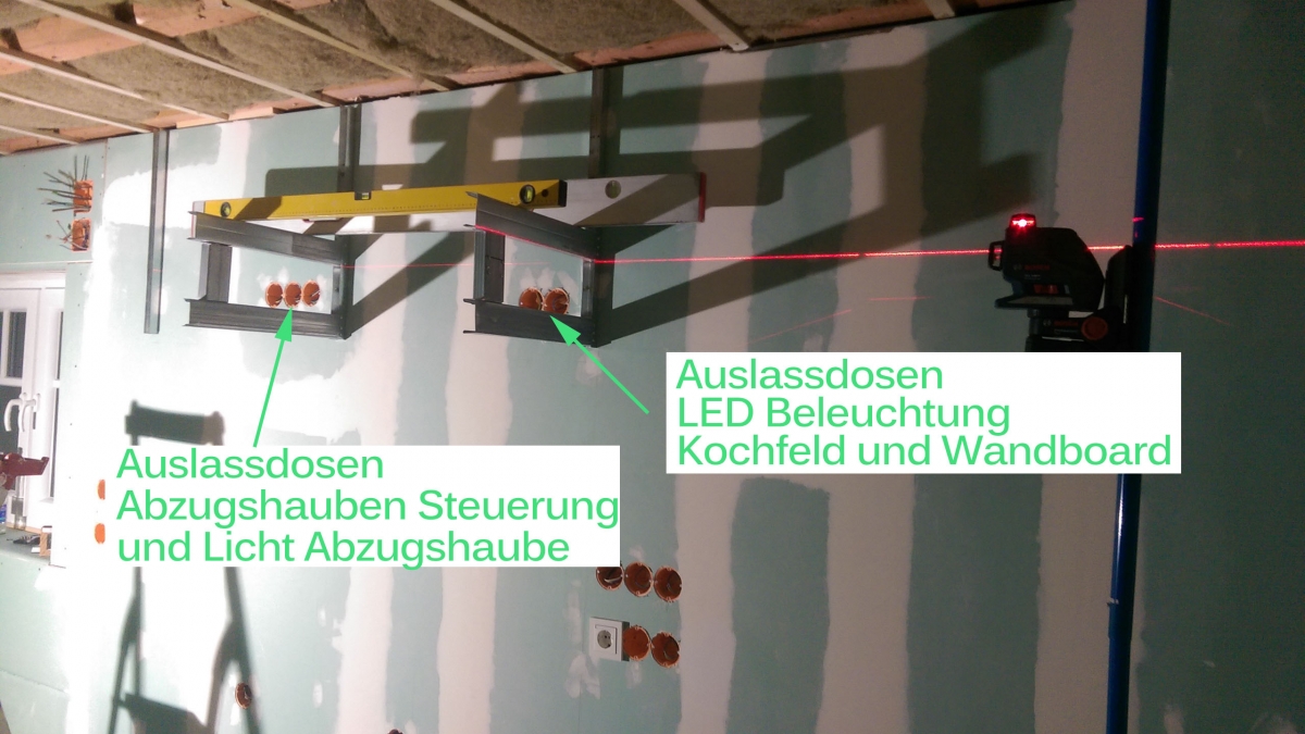
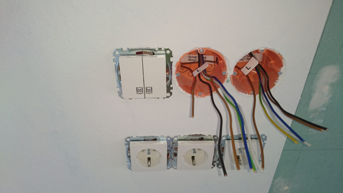
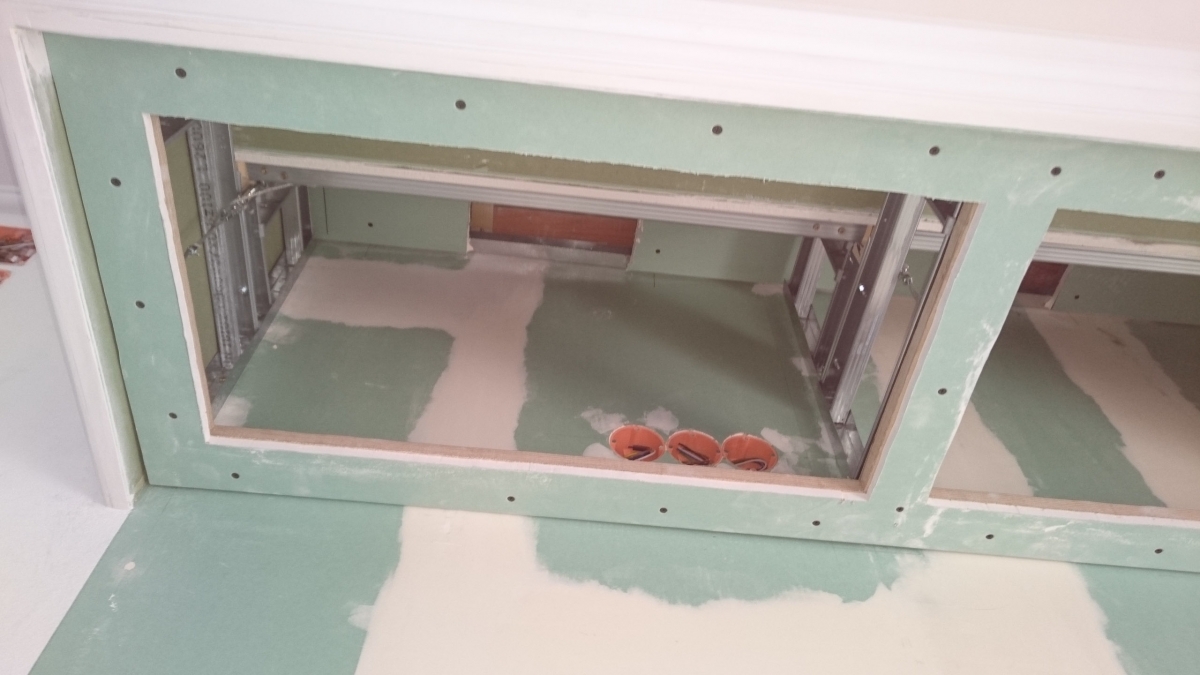
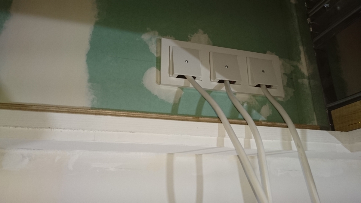
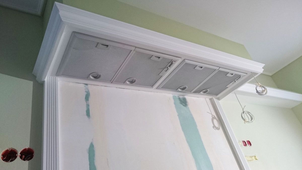
An optical and technical highlight of the kitchen is the extractor hood in the style of a chimney hood followed by a wallboard. Already in the planning phase some things had to be considered. On the one hand, the overall width of the construction had to be determined, as the stud frame with the corresponding beams had to be fixed at the backwall of the shell. On the other hand, the electrical installation had to be prepared for the operation of the built-in extractor hoods and the LED lighting profiles. Ultimately, the ventilation pipes and their guidance must be planned. After all it is about two 150 mm exhaust pipes – so it is in the truest sense of the word “haze” behind it. The used fan modules type LB75564 IQ 300 each have 2 motors installed. The fan components were also modified slightly electrically. On the one hand, the spots were rebuilt to LED so that a spot after conversion has just 1 watt electrical power and on the other hand, the switches on the hood were completely shut down since the light and the ventilation levels later are controlled via a switch within the switch program used. Inside the construction are 5 outlet boxes.
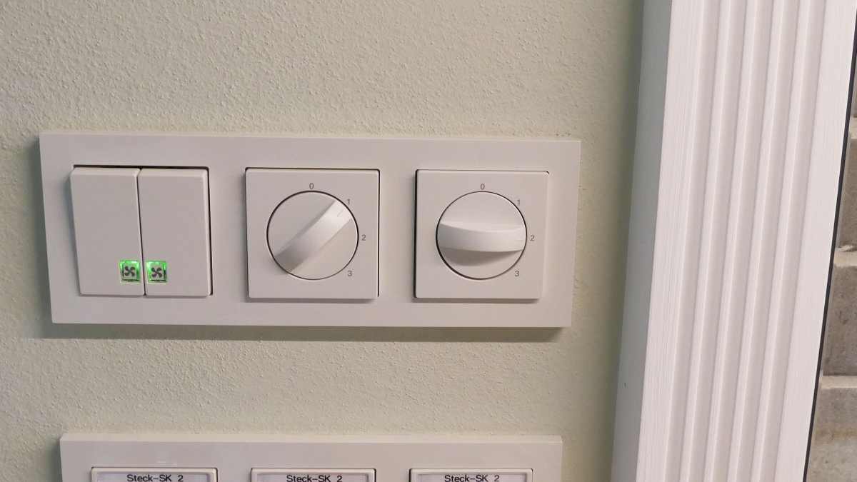
The switching of the fan modules via the separate switch would not have been necessary because the rotary switches also have an off position, but firstly it offers more comfort in my opinion and secondly looks better (and spares the three-position rotary switch). A green control LED confirms that the hoods are switched on.
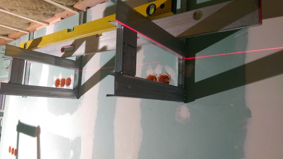
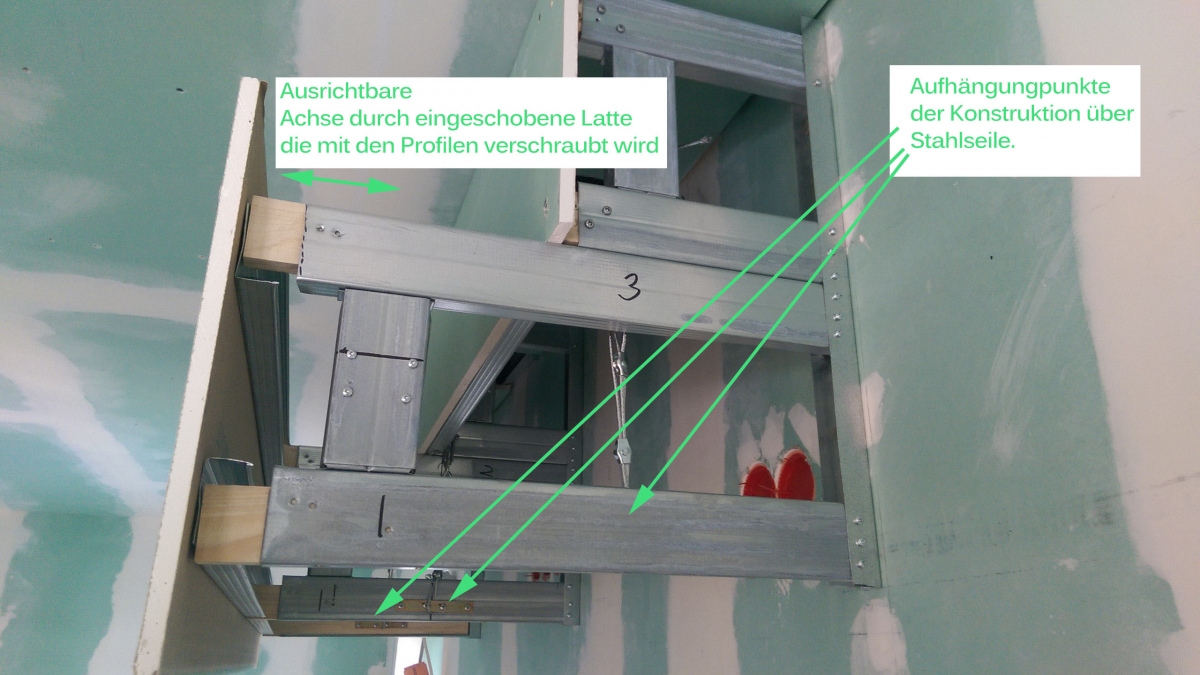
As can be seen in the first picture, the basic construction of the chimney hood was also made of metal profiles for drywall construction. Here is some imagination needed on how such a construction can be created efficiently and safely. A laser and some spirit levels and help in the exact alignment of the construction.
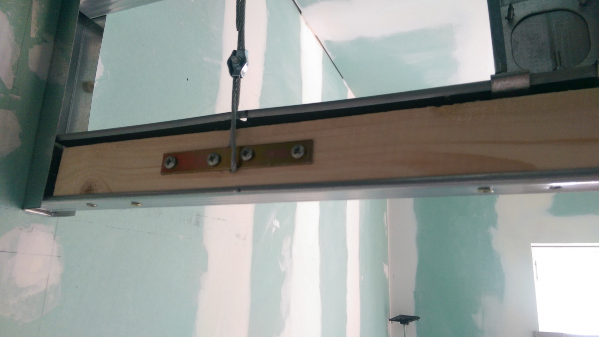
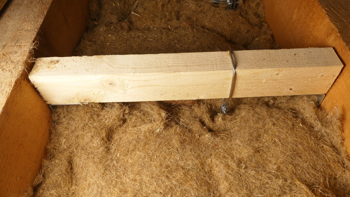
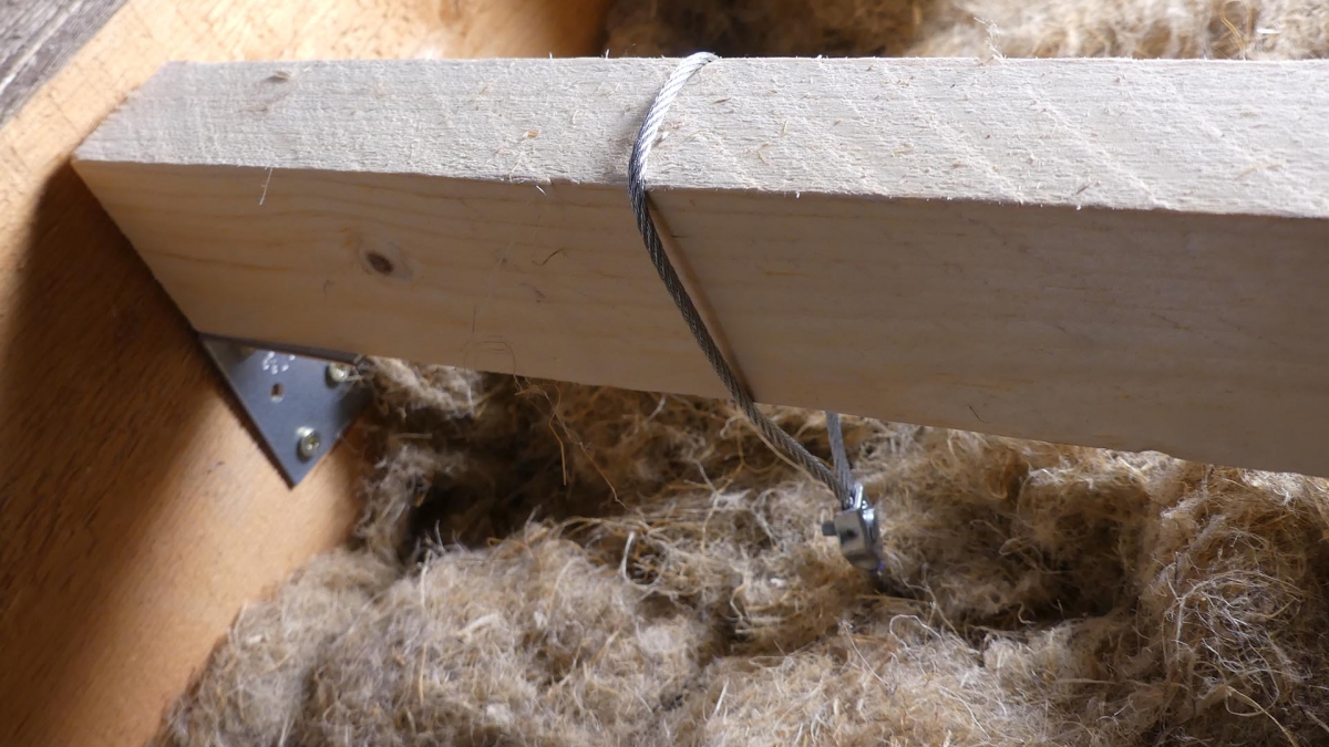
A steel cable suspension at three points ensures load transfer. Because the loft is located above the kitchen, the suspension could be realized between two beams. Otherwise, the suspension must be adapted to local circumstances.
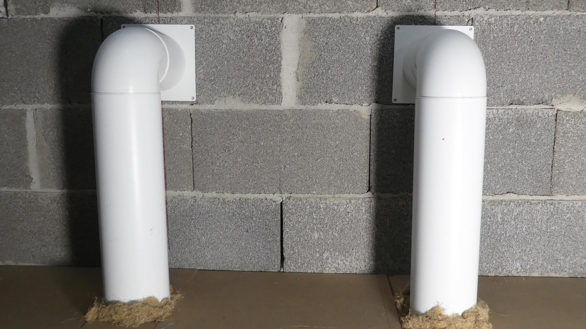
The ducting to the outside of the two fan blocks has more of something of an exhaust outlet of a ship than of an extractor hood.
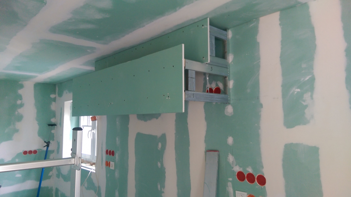
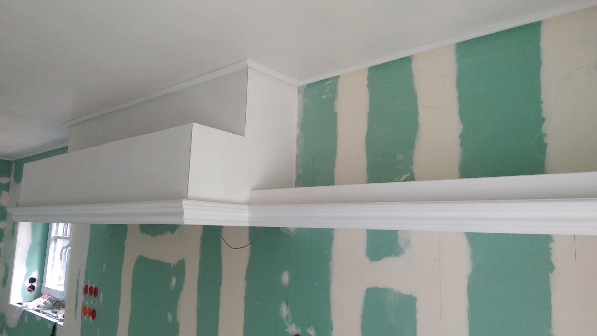
Unfortunately, it was not possible to create pictures of the construction of the adjoining wallboard. The wallboard is much easier to build than the hood construction. Either you reach for metal angles or you set some IKEA LACK wall shelves and cover them with plasterboards. The following picture shows the already planked and filled overall construction, in addition the stucco moldings were attached.
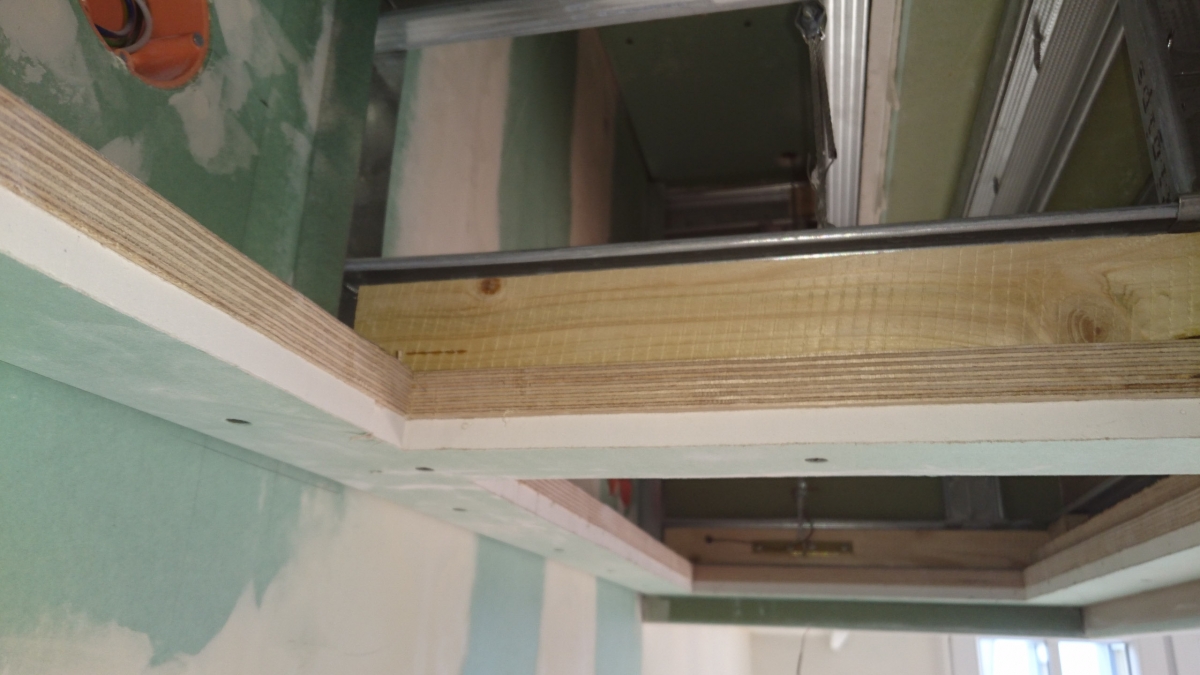
One of the later steps is the insertion of a stable multiplex board from below into the construction. Previously, the cutouts for the fan parts were created in the multiplex board. A plasterboard is then screwed onto the multiplex board, which is then troweled and painted (the first coat is here with latex paint to provide protection against rising damp). Due to the sufficiently large openings, the wiring within the structure with the final mounted outlet boxes can also be completed. As can be seen in the pictures, the planking of the construction with projection to the base plate, which receives the fan modules, was executed. This has a practical and aesthetic reason – the overhang serves as a light shutter for the LED profile to be mounted later since indirect light is much more pleasing to the human eye than visible light sources.
In the last step, the two fan modules are mounted. So far the extractor hood is “kitchen ready”.

